 English
Views: 11 Author: Site Editor Publish Time: 2026-08-12 Origin: Site


Modern commercial refrigeration faces a distinct engineering friction. The market demands smaller equipment footprints to maximize retail or clinical space. This directly conflicts with the physical need for higher thermal rejection capacities. Traditional bulky heat exchangers fail to navigate this spatial reality. Standard shell-and-tube models require massive installation volumes. Oversized fin-and-tube designs consume critical chassis space. Neither option meets the strict spatial requirements of modern refrigerated display cabinets or medical coolers without sacrificing energy efficiency. Forcing oversized components into small enclosures often degrades compressor lifespan through inadequate heat dissipation.
Engineers need a viable architectural solution. The Tube Plate Condenser solves this exact problem. It leverages high-turbulence fluid dynamics and optimized surface areas to fit within tight chassis constraints. By bonding refrigerant-carrying tubes directly to flat, conductive plates, this design maximizes heat exchange in a fraction of the traditional footprint. You can achieve aggressive cooling targets while maintaining a slim appliance profile. The resulting architecture supports high-capacity cooling without overwhelming the physical limits of the cabinet.
Spatial Optimization: A tube plate condenser significantly reduces the required installation volume compared to legacy systems, making it the standard for compact cooling cabinets.
Enhanced Heat Transfer: Thin plates and small-diameter tubes induce high internal turbulence, maximizing heat exchange rates per square inch of the condenser.
Reduced Refrigerant Charge: The internal volume of a plate mounted condenser coil is typically lower, aiding in compliance with strict environmental regulations regarding refrigerant limits.
Maintenance Trade-offs: While highly efficient, the compact nature of these condensers requires strict filtration and maintenance protocols to prevent micro-channel fouling and air-side pressure drops.
Designing a cooling system for tight spaces requires strict adherence to specific success criteria. You must achieve maximum heat rejection within a minimal physical footprint. Acoustic levels must remain acceptable for indoor commercial environments. A compact refrigeration condenser must balance these competing demands perfectly. If the condenser is too large, it encroaches on the usable storage volume of the cabinet. If it is too small, the system fails to reject enough heat. This leads to elevated head pressures, increased energy consumption, and premature compressor failure. Hitting the exact thermal target requires precise engineering.
We evaluate success in tight spaces using three primary metrics. First, volumetric heat rejection measures the amount of thermal energy dissipated per cubic inch of condenser space. Second, airflow resistance tracks the static pressure drop across the coil face, which determines fan size requirements. Third, acoustic output monitors the decibel level generated by air moving through the heat exchanger matrix. You must optimize all three variables simultaneously to build a viable commercial cabinet.
Thermal density presents a major physics challenge in cabinet design. Rejecting high heat loads from small enclosures is inherently difficult. Airflow restrictions compound the problem. Compact cabinets often sit flush against walls or integrate directly into counters. This limits the volume of ambient air available for heat dissipation. Ambient temperature impacts also play a critical role. When a cabinet operates in a hot commercial kitchen, the temperature delta between the ambient air and the refrigerant shrinks. The condenser must work significantly harder to reject the same amount of heat. High thermal density requires a highly efficient heat exchange surface to compensate for restricted airflow.
Modern systems often utilize R290 propane. This refrigerant offers excellent thermodynamic properties but carries strict charge limits due to flammability regulations. You cannot simply pump more refrigerant into a bulky coil to compensate for poor airflow. The condenser must extract maximum heat from a minimal volume of R290. This regulatory constraint forces engineers to abandon large-volume coils in favor of high-efficiency, low-volume alternatives.
Legacy architectures cannot support modern compact applications. Traditional static condensers fall short in almost every metric. Serpentine or two-dimensional tube arrangements secured to an appliance's back wall limit design flexibility. They rely entirely on passive convection. This offers an inadequate surface area-to-volume ratio for high-capacity cooling demands. Static back-wall designs expel heat too slowly for rapid pull-down times. They also dictate the exterior dimensions of the cabinet, forcing designers to build around the condenser rather than concealing it. Modern refrigeration demands active, high-density heat rejection that legacy static coils simply cannot provide.
Spatial Efficiency Metrics Comparison
System Type | Average Volume Required | Heat Rejection Capacity | Airflow Dependency |
|---|---|---|---|
Static Back-Wall Coil | High (External) | Low | Passive Convection |
Standard Fin-and-Tube | Moderate (Internal) | Moderate to High | High (Forced Air) |
Plate Condenser | Very Low (Internal) | High | Moderate (Directed Air) |
When tearing down older display cases in the field, we often find oversized fin-and-tube coils packed with dirt. The fans work overtime, but the air simply bypasses the blocked fins. This is a direct result of poor spatial planning. The coil was too thick for the chassis, leaving no room for proper filtration or maintenance access. Upgrading to a slimmer profile solves this historical design flaw.
The structural design of a tube plate condenser relies on precise mechanical integration. Manufacturers bond or braze copper or steel tubes directly to flat metal plates. This creates a rigid, highly conductive matrix. The brazing process ensures a continuous thermal bridge between the tube wall and the plate surface. This eliminates microscopic air gaps that would otherwise insulate the tube and degrade heat transfer. The resulting structure is incredibly robust. Unlike fragile aluminum fins that bend under light pressure, the solid plate withstands physical impacts during transport and installation. This rigidity translates to long-term reliability in demanding environments.
During fabrication, automated CNC benders shape the tubing into tight serpentine patterns. This precision prevents kinking, which would otherwise restrict refrigerant flow and cause localized pressure spikes. Once formed, the tube matrix is pressed against the steel or aluminum plate. We use specialized conductive adhesives or furnace brazing to permanently join the two metals. Furnace brazing is preferred for commercial applications. It melts a filler metal that flows into the microscopic gaps between the tube and plate via capillary action. This creates a permanent, highly conductive bond that will not degrade under constant thermal cycling.
Mounting the coil directly to a plate structure serves dual purposes. First, it drastically enhances the structural integrity of the entire heat exchanger assembly. The plate acts as a rigid chassis for the tubing. Second, the plate mounted condenser coil functions as an extended secondary heat transfer surface. As hot refrigerant flows through the tubes, heat conducts rapidly into the flat plate. The plate then radiates and convects this heat into the surrounding air. This effectively multiplies the surface area available for thermal rejection without increasing the overall depth of the component. You get the performance of a much larger coil in a slim, flat profile.
After brazing, we subject the plate assemblies to rigorous burst testing. We pressurize the internal galleries well beyond standard operating pressures. The solid plate prevents the thin-walled tubes from ballooning or rupturing. This structural reinforcement is necessary when operating in high-ambient conditions where head pressures spike unpredictably.
Industry standards have shifted away from large diameter tubing. Modern refrigerated display cabinets now utilize small diameter alternatives, such as 5mm copper tubes. This transition fundamentally improves condenser performance. Smaller tubes increase the internal surface-area-to-volume ratio. More refrigerant comes into direct contact with the tube wall. This improves the overall heat transfer coefficient within the exact same physical envelope. Smaller tubes also require less total internal volume. This allows manufacturers to reduce the system's overall refrigerant charge. Lowering the charge helps cabinets comply with increasingly strict environmental regulations regarding global warming potential limits.
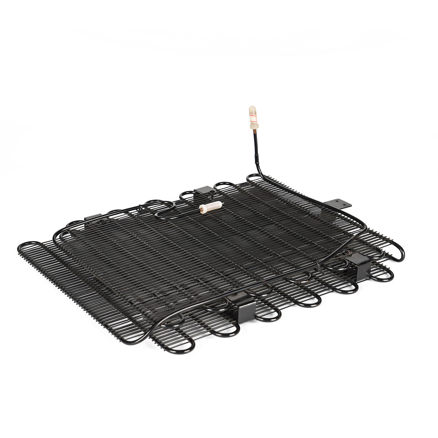
Fluid dynamics dictate the efficiency of any heat exchanger. A tube plate condenser excels by inducing high internal turbulence. The combination of narrow internal galleries and thin plates forces the refrigerant into a turbulent flow state. In legacy designs with large tubes, refrigerant often flows in a laminar pattern. Laminar flow creates a boundary layer of insulating fluid against the tube wall, slowing heat transfer. High turbulence breaks this boundary layer. It constantly mixes the refrigerant, bringing hotter fluid into direct contact with the conductive walls. This accelerates heat exchange significantly compared to laminar flow designs.
Air-side surface area optimization is equally critical. The flat plate design maximizes physical contact with ambient air. Even when fan-forced airflow is limited by the cabinet's exterior design, the broad surface area ensures efficient heat dissipation. Engineers optimize the spacing and orientation of these plates to reduce aerodynamic drag. This allows low-velocity fans to push air across the condenser without generating excessive noise or consuming high wattage. The aerodynamic profile prevents air from bypassing the heat exchange surfaces. Every cubic foot of air moving through the chassis absorbs maximum thermal energy before exiting the cabinet.
Pairing the condenser with the right fan motor is necessary for optimal performance. We typically specify electronically commutated (EC) motors. EC motors provide variable speed control, allowing the system to ramp up airflow only when the thermal load demands it. The flat plate design presents a predictable static pressure curve, making it easy to program the EC motor for maximum electrical efficiency. You avoid the energy waste associated with constant-torque shaded pole motors.
Evaluating temperature gradients across the plate requires rigorous thermal mapping. Engineers use infrared thermography during the prototyping phase to visualize heat distribution. A well-designed plate will show a smooth, uniform temperature gradient from the refrigerant inlet to the outlet. Localized hot spots indicate poor internal flow distribution or inadequate bonding between the tube and the plate. Uniform heat rejection ensures that the entire surface area contributes to cooling. If certain sections remain cold while others overheat, the condenser operates below its rated capacity. Thermal mapping guarantees that the physical geometry matches the required thermal load.
In our testing labs, we place prototype cabinets in environmental chambers. We push the ambient temperature to 110°F with high humidity to simulate worst-case commercial kitchen conditions. We attach thermocouples directly to the condenser inlet, midpoint, and outlet. We monitor the subcooling values closely. If the subcooling drops below the target threshold, it means the plate is not rejecting enough heat. We then adjust the fan blade pitch or increase the plate surface area. We also measure the air velocity exiting the condenser face using an anemometer. We look for dead zones where air stalls. Stalled air acts as an insulator. By tweaking the internal baffles of the cabinet chassis, we can force the air to sweep evenly across the entire plate surface.
Comparing condenser architectures reveals distinct operational advantages depending on the application. The bulky, cylindrical footprint of a shell-and-tube heat exchanger contrasts sharply with the slim, modular profile of plate designs. Shell-and-tube systems require massive volumes of water and complex secondary cooling loops. Upgrading to high-efficiency plate designs can sometimes eliminate the need for these secondary loops or external cooling towers in specific commercial facility retrofits. You can achieve direct-expansion cooling in a much smaller footprint. Shell-and-tube technology remains reserved for large industrial plants. Tube plate designs dominate decentralized, compact commercial units where space is at an absolute premium.
Beyond footprint, weight is a major factor in cabinet design. Heavy shell-and-tube or thick finned coils require reinforced steel chassis frames. A plate condenser weighs significantly less. This allows manufacturers to use lighter gauge metals for the cabinet body, reducing shipping costs and making the unit easier to maneuver on the retail floor. The weight reduction directly impacts the overall manufacturing budget.
Traditional fin-and-tube designs also struggle against plate architectures in specific environments. Durability is a major differentiator. Aluminum fins are notoriously fragile. Routine maintenance, accidental impacts, or high-pressure cleaning can easily crush the fins. Crushed fins block airflow and instantly degrade cooling capacity. The structural rigidity of a solid metal plate eliminates this risk. You can clean a plate condenser aggressively without fear of damaging the heat exchange surface. This robust construction ensures that the unit maintains its factory-rated efficiency years after installation.
Fouling resistance further separates the two designs. Fin-and-tube coils act like air filters. They trap dust, grease, and debris between the tightly spaced fins. This accumulation chokes airflow and insulates the tubes. A tube plate condenser offers superior fouling resistance. The flat, smooth surfaces provide fewer catch points for airborne debris. While dust will eventually settle on the plates, it does not embed itself deeply into narrow crevices. This makes visual inspections easier and routine cleaning much faster. The system suffers less efficiency degradation between maintenance intervals.
Consider a reach-in cooler located near a bakery oven. The air is thick with flour dust and vaporized shortening. A standard finned coil will plug solid within three months. The compressor will overheat and trip on high head pressure. A technician will spend an hour applying chemical coil cleaners and carefully brushing the delicate fins to restore airflow. In the exact same environment, a plate condenser will accumulate a thin layer of dust on its flat surface. The technician can wipe it clean with a damp cloth in sixty seconds. The operational uptime increases dramatically.
Comparison of Condenser Architectures
Feature | Tube Plate Condenser | Fin-and-Tube Condenser | Shell-and-Tube Condenser |
|---|---|---|---|
Footprint | Ultra-compact, slim profile | Moderate to large | Massive, cylindrical |
Durability | High (rigid plates) | Low (fragile fins) | Very High (heavy gauge steel) |
Fouling Resistance | Excellent (smooth surfaces) | Poor (traps debris easily) | N/A (water-cooled internal) |
Primary Application | Compact commercial cabinets | Standard refrigeration/HVAC | Large industrial plants |
Refrigerant Charge | Very Low | Moderate | High |
Successful implementation begins with rigorous 3D spatial planning. During the cabinet design phase, engineers must model the exact placement of the condenser. You cannot treat the heat exchanger as an afterthought. Installation best practices dictate that condensing units must be oriented correctly to prevent airflow choking. The intake and exhaust pathways must remain completely unobstructed by compressors, wiring harnesses, or structural brackets. Technicians also need physical access to the unit. If the condenser is buried behind immovable panels, routine cleaning becomes impossible. Proper 3D modeling ensures optimal airflow and guarantees serviceability in the field.
Managing internal pressure drops is the primary engineering trade-off with this technology. Higher turbulence and smaller diameter tubes inherently increase the resistance to refrigerant flow. This creates a higher pressure drop across the condenser coil. If ignored, this pressure drop starves the expansion valve and forces the compressor to work outside its design envelope. You must size compressors accordingly to maintain system balance. Engineers often select compressors with slightly higher volumetric capacities to overcome this resistance. Careful matching of the compressor, expansion device, and condenser geometry ensures that the system delivers the required cooling capacity without excessive energy consumption.
The increased pressure drop of a compact coil directly impacts capillary tube sizing. If you use a standard capillary tube chart designed for a finned coil, you will starve the evaporator. You must calculate the exact pressure drop across the plate condenser and shorten the capillary tube accordingly to maintain the correct mass flow rate. System balancing requires precise mathematical modeling before physical prototyping begins.
Operating a compact condenser in commercial environments requires strict fouling and maintenance protocols. Grocery stores and commercial kitchens generate massive amounts of airborne dust, flour, and aerosolized grease. Even with superior fouling resistance, preventative maintenance is non-negotiable. Facility managers must implement regular air-side cleaning schedules. Technicians should wipe down or blow out the plates to prevent airflow blockages. If debris accumulates heavily, the condenser loses its ability to reject heat. The cabinet will fail to maintain safe food storage temperatures. Clear maintenance documentation must accompany every unit deployed into the field.
Integration with existing cabinet chassis requires careful mechanical design. When retrofitting older cabinets or designing new mounts, engineers must isolate vibration. Compressors generate harmonic vibrations that can travel through rigid copper lines and fracture brazed joints on the plate. Rubber isolation grommets and flexible discharge lines mitigate this risk. You must also manage condensate drainage effectively. While condensers operate hot, ambient humidity can occasionally cause issues during off-cycles or defrost periods. The chassis design must ensure unobstructed airflow to the coil while directing any incidental moisture safely away from electrical components.
When installing a plate condenser into a new cabinet chassis, follow these specific mechanical steps:
Mount the base plate using rubber isolation dampeners to absorb compressor harmonics.
Align the condenser face perpendicular to the primary cooling fan to ensure even air distribution.
Route the copper discharge line with a minimum of two 90-degree bends to create a vibration-absorbing trap.
Braze the connections using a 15% silver alloy while flowing dry nitrogen to prevent internal oxidation.
Pressurize the entire assembly to 300 PSI with nitrogen and hold for twenty-four hours to verify joint integrity.
Apply a conformal coating to the exposed plate edges if the cabinet will operate in a highly corrosive environment, such as a coastal seafood market.
Run computational fluid dynamics (CFD) simulations on your proposed cabinet chassis to verify adequate airflow across the condenser face.
Specify 5mm copper tubing in your design requirements to minimize the total system refrigerant charge.
Install rubber isolation grommets on all mounting brackets to protect brazed joints from compressor vibration.
Draft a mandatory quarterly maintenance schedule requiring technicians to wipe down the flat plate surfaces.
A: A tube plate condenser is a specialized heat exchanger where refrigerant-carrying tubes are mechanically bonded or brazed to flat metal plates. This design maximizes the available surface area for heat transfer while maintaining a minimal physical footprint, making it ideal for tight spaces.
A: The flat plate acts as an extended heat sink, rapidly pulling heat away from the tubes. Simultaneously, the narrow internal pathways induce fluid turbulence. This turbulence breaks the thermal boundary layer, significantly increasing the rate of heat rejection to the ambient air.
A: Yes, they can replace them in specific commercial and compact applications to save space and reduce system complexity. However, traditional shell and tube models are still required for massive industrial cooling loads where water-cooled heat rejection is necessary.
A: These units require frequent visual inspections and routine cleaning of the air-side plates. Preventing dust and grease buildup is critical, as accumulated debris can severely restrict airflow, insulate the plates, and rapidly degrade the system's overall cooling performance.
A: Replacing large diameter tubes with 5mm alternatives reduces the required refrigerant charge. It also increases the internal surface-area-to-volume ratio. This leads to higher overall system efficiency and better thermal transfer rates within tight cabinet spaces.
A: Yes. The restrictive nature of small diameter tubes and high-turbulence internal designs naturally increases fluid resistance. This results in a higher pressure drop, requiring careful compressor matching and precise system balancing to ensure reliable operation.
A: Static serpentine condensers rely entirely on passive ambient air convection and take up significant external space. In contrast, tube plate condensers offer much higher thermal density and utilize active heat rejection, all contained within a concealed, compact chassis.


