 English
Views: 0 Author: Site Editor Publish Time: 2026-09-16 Origin: Site


If you have spent any time designing commercial cooling units recently, you know the landscape has fundamentally shifted. Driven by aggressive global F-gas regulations and the imminent phase-out of high-GWP synthetic refrigerants, carbon dioxide (R744) is no longer just an alternative. It is the industry standard. However, R744 is a beast to tame. Because CO2 operates at discharge pressures that absolutely dwarf traditional hydrofluorocarbons (HFCs), legacy heat exchanger designs frequently fail in the field, suffering from ruptured tubes and dismal thermal efficiency.
At the end of the day, a CO2 system's performance lives or dies by its physical geometry. You cannot just swap refrigerants and hope for the best. Engineers must meticulously manipulate the micro-geometry of the heat exchanger to hit the required thermal targets. In this breakdown, we are going to strip away the academic theory and look at the actual physics of thermal transfer. We will focus specifically on how tweaking tube diameters and wire-on-tube layouts dictates the energy efficiency, burst strength, and operational lifespan of modern commercial cooling setups.
Smaller Tubes Drive Efficiency: Dropping the tube diameter spikes the internal heat transfer coefficient and slashes the required refrigerant charge. The catch? You have to aggressively manage the pressure drop.
Wire Layout Controls the Air: The pitch and alignment of your external wires dictate both your heat dissipation area and your aerodynamic drag.
Bundy Tubes Are Mandatory: Standard copper will not survive R744. Double-walled, brazed steel tubes provide the sheer structural muscle needed for transcritical pressures.
The Field Balance: The holy grail of condenser design is finding the exact empirical sweet spot between maximum thermal output and enough airflow space to prevent dust fouling.
Let's look at the current trajectory of the commercial refrigeration sector. Industry data shows a massive push toward high-density, micro-geometry systems. Retailers want maximum internal display volume, which means OEMs are forced to shrink the mechanical compartment. You have to reject more heat in less physical space. This aggressive space constraint makes a highly optimized commercial refrigerator condenser absolutely vital for keeping the compressor alive and energy bills low.
In a traditional vapor-compression cycle, the condenser cools and condenses high-pressure gas into a liquid. But CO2 plays by different rules. On a hot summer day, ambient temperatures easily exceed CO2's critical point (31.1°C or 88°F). When this happens, the system enters transcritical operation. The refrigerant never actually condenses into a liquid; instead, it cools as a dense supercritical fluid. While thermodynamic purists call it a "gas cooler," anyone turning a wrench in the field still calls it a condenser.
Because these R744 systems routinely run at pressures exceeding 100 bar (1450 psi), structural integrity is your first priority. The component must contain these extreme forces safely while transferring heat efficiently within the cramped confines of a vending machine or supermarket display case.
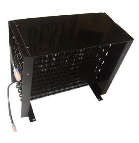
To squeeze every drop of efficiency out of a cooling deck, you need to understand the path of refrigeration heat rejection. In a wire-and-tube setup, heat transfer happens in three distinct phases. First, internal convection pulls heat from the scorching CO2 fluid into the inner wall of the steel tube. Second, conduction drives that thermal energy through the tube wall and out into the welded steel wires. Finally, external convection takes over, dumping the heat from the wires into the ambient air.
Why do we still rely heavily on wire-on-tube configurations for light commercial gear? Because it works brilliantly in dirty environments. Aluminum fin-and-tube coils are notorious for acting like giant air filters; they trap dust, grease, and pet hair until airflow completely stops. In contrast, the cylindrical profile of a steel wire minimizes boundary layer separation. Air slips around the wires easily. This drastically reduces dead zones where debris can settle, keeping the coil breathing freely in high-traffic retail stores.
If you ask any seasoned HVAC/R engineer, they will tell you the internal diameter (ID) of the refrigerant tube is the single most critical variable in your design. It is a constant tug-of-war between thermal transfer and hydraulic resistance.
Let’s look at the fluid dynamics. Shrinking the tube's internal diameter forces the dense CO2 to move faster. This higher fluid velocity kicks up the Reynolds number, creating aggressive turbulent flow. Why does this matter? Because turbulence continuously scrubs the inner tube wall, stripping away the insulating boundary layer of stagnant gas. This drastically spikes your internal heat transfer coefficient.
Practically speaking, smaller tubes—like moving from an 8.0mm OD down to a 4.76mm OD—also slash the internal volume of the coil. For an OEM, this is a massive win. It minimizes the total R744 charge required, which cuts upfront material costs and significantly lowers safety risks if a line bursts.
However, physics always demands a toll. Pushing a dense supercritical fluid through a tiny passageway exponentially increases frictional loss. This creates a severe pressure drop across the condenser. If you choke the flow too much, your compressor has to work overtime to push the required mass flow rate. The extra amp draw from the compressor will instantly wipe out any thermal efficiency gains you made with the smaller tube. Finding the exact "sweet spot" is where computational fluid dynamics (CFD) and rigorous lab testing come into play.
While tube sizing handles the internal fluid, your external wire layout dictates how the unit breathes. The geometry of a high-performance steel wire condenser is never a guess. It is a highly calibrated matrix.
Wire pitch is the gap between each parallel wire welded to your serpentine tube. On paper, tighter pitch means more steel, more surface area, and better cooling. But out in the real world, thermal performance does not scale linearly with wire density. If you pack the wires too tightly (e.g., under 4mm pitch), you create an aerodynamic brick wall. The boundary layers of air around adjacent wires overlap. Instead of flowing through the coil, the air stalls, trapping a blanket of hot air against the tubes.
This brings us to the "fouling factor." A condenser running in a greasy restaurant kitchen faces a totally different reality than one in a clean pharmacy. When dust bridges the gap between tightly packed wires, it acts as a thermal blanket. Head pressure spikes, and the compressor starts screaming. An optimized layout balances surface area with enough breathing room to allow for natural draft convection, ensuring the unit stays relatively self-cleaning.
Design Strategy | Typical Specs | Primary Advantage | Ideal Application Scenario |
|---|---|---|---|
High-Density Forced Air | 4.76mm Tube OD, 4-5mm Wire Pitch | Maximum thermal output per square inch. | Indoor, climate-controlled supermarket coolers with powerful fan motors. |
Low-Maintenance Static | 6.0mm - 8.0mm Tube OD, 6-8mm Wire Pitch | Highly resistant to dust fouling; low pressure drop. | Outdoor beverage vending machines, commercial kitchens (natural draft). |
Given the extreme operating pressures of R744, standard single-wall copper or aluminum tubes are a liability. They will fatigue and rupture. This harsh reality has forced the industry to universally adopt the Bundy tube condenser for commercial applications.
If you are unfamiliar with the manufacturing process, a Bundy tube is a specialized, double-walled steel tube. A copper-coated steel strip is rolled 720 degrees around a mandrel to form a dual-layer wall, then sent through a continuous brazing furnace. The molten copper fuses the overlapping steel layers together. The result is a seamless, incredibly rigid tube.
Because CO2 systems frequently see discharge pressures hitting 120 bar during a summer heatwave, structural integrity is non-negotiable. Real-world burst testing shows that quality Bundy tubing can comfortably withstand pressures well beyond 130 bar, leaving single-wall materials in the dust.
Beyond burst strength, these units live in brutal, corrosive environments. To prevent premature rust, top-tier manufacturers run the welded assemblies through a cathodic electro-deposition (e-coating) process. This bakes on a uniform, microscopic layer of epoxy (typically 15-20 micrometers thick) that blocks corrosion without acting as a thermal insulator.
Designing or sourcing the right component is an exercise in multivariable calculus. You cannot change one parameter without affecting the rest. When you are spec'ing a wire tube CO2 condenser, you need to match the geometry to the exact field conditions.
For example, if you are building an outdoor ice merchandiser that relies on static natural convection, specify a 6.0mm or 8.0mm Bundy tube with a wider wire pitch (around 6mm to 8mm) and a thicker 1.6mm steel wire. This guarantees low maintenance and steady airflow even when covered in street dust.
Conversely, if you are designing a compact under-counter medical fridge with a high-velocity fan, you can drop down to a 4.76mm tube with a tight 4mm wire pitch. This shrinks your footprint, minimizes your R744 charge, and maximizes heat rejection, provided your fan can overcome the aerodynamic static pressure.
Mastering CO2 condenser design comes down to respecting the micro-geometry. By strategically balancing smaller Bundy tube diameters with a field-tested wire pitch, you can drastically improve heat rejection, lower the refrigerant charge, and keep the compressor running effortlessly for years. A properly spec'd unit doesn't just save energy—it protects your brand's reputation by preventing catastrophic high-pressure failures.
If you are an OEM or contractor looking to transition to reliable R744 cooling components, you need a manufacturing partner who actually understands these thermodynamic trade-offs. Don't leave your system's reliability to chance. Evaluate your specific cooling loads, airflow constraints, and pressure requirements, and explore precision-engineered solutions at https://www.retekool.com to find the exact condenser geometry that matches your next project.
Wire tube condensers are incredibly resistant to dust clogging. Their cylindrical aerodynamic profile allows air to slip past easily, making them largely self-cleaning. This makes them the go-to choice for low-maintenance commercial refrigerators in high-traffic or greasy environments where traditional aluminum fins would choke and fail.
CO2 (R744) operates at brutal pressures, often exceeding 100 bar in transcritical mode. Bundy tubes are double-walled, copper-brazed steel tubes that offer massive burst strength. They safely contain these extreme pressures without fatiguing, which standard single-wall copper tubes simply cannot do.
In standard subcritical operation, pressures sit around 40 to 60 bar. However, during hot summer months when the system enters transcritical mode, discharge pressures routinely spike to between 90 and 120 bar. Quality condensers are pressure-tested well beyond 130 bar to ensure absolute safety.
Dust acts as a thick thermal blanket. If your wire pitch is too tight, airborne debris bridges the gap between wires and blocks airflow. This kills your external convection, forcing the compressor's head pressure to skyrocket, which burns more electricity and eventually leads to mechanical failure.
Usually, no. While a larger tube lowers the internal pressure drop, it drastically slows down the velocity of the CO2 fluid. Slower fluid means less turbulence, which drops the internal heat transfer rate. Modern designs favor smaller tubes (like 4.76mm) to keep velocity high and reduce the total refrigerant charge.
Because of their open geometry, maintenance is incredibly simple. You do not need harsh chemicals or high-pressure washers. A standard stiff-bristled nylon brush or compressed air is usually all it takes to knock away accumulated surface dust during routine quarterly maintenance, instantly restoring optimal airflow.


