 English
Views: 9 Author: Site Editor Publish Time: 2026-08-08 Origin: Site


Unlike traditional solar thermal systems that rely entirely on direct solar irradiance, thermodynamic systems operate on ambient temperature, fundamentally changing the rules of installation and site planning. Property owners and facility managers often apply legacy solar PV or solar thermal positioning logic to thermodynamic systems. This results in sub-optimal installations, compromised refrigerant flow, and failure to achieve the promised Coefficient of Performance (COP), especially in challenging climates. Establishing a technical framework for positioning a thermodynamic solar panel requires understanding refrigerant phase changes, airflow dynamics, and structural constraints. This guide breaks down the exact specifications for mounting, orienting, and integrating these systems to guarantee maximum heat absorption and system longevity. Proper site evaluation prevents compressor starvation and ensures the system extracts maximum thermal energy from the surrounding environment.
Ambient Heat Over Direct Sunlight: While direct sunlight provides a performance boost, thermodynamic panels primarily extract heat from ambient air, allowing for flexible placement in shaded areas or on north-facing walls (in the Northern Hemisphere).
Strict Orientation Rules: Panels must typically be installed in a "landscape" orientation to ensure proper circulation of the liquid refrigerant and prevent compressor starvation.
Mandatory Tilt for Runoff: Even in flat installations, a minimum tilt of 15 degrees is required to facilitate the runoff of rainwater, condensation, and defrost cycles.
Proximity to the Compressor: Positioning must balance optimal outdoor airflow with the shortest possible line set distance to the indoor compressor to minimize pressure drops and thermal losses.
Energy Density Contrast: Traditional solar thermal collectors absorb 900–1000 W/m² under peak direct sunlight, whereas a thermodynamic solar panel relies on continuous, lower-intensity ambient heat exchange, making unobstructed airflow more critical than direct sun exposure.
To evaluate positioning options, buyers must first understand what the panel is actually doing. It acts as an evaporator in a heat pump cycle rather than a traditional solar collector. Grasping this concept is the foundation for making informed installation decisions. The panel operates as a massive heat exchanger, capturing low-grade thermal energy from the atmosphere and transferring it to a refrigerant fluid.
The refrigerant typically enters the panel as a liquid at sub-zero temperatures, often between -20°C and -30°C. It vaporizes upon contact with ambient heat. This phase change is the core mechanism of heat extraction. Because the fluid is significantly colder than the outside air, heat naturally flows from the air into the panel, boiling the refrigerant into a gas.
Traditional solar thermal systems can absorb 900–1000 W/m² of heat under direct peak sunlight but drop to zero at night. A thermodynamic solar panel absorbs heat 24/7 from the ambient air, wind, and rain, even in complete shade. This continuous operation provides a steady supply of energy regardless of the time of day. The system does not shut down when the sun sets; it continues to pull thermal energy from the night air.
Direct sunlight and wind offer secondary benefits. They accelerate the phase change, improving efficiency, but they are not strictly necessary for baseline operation. The system will function as long as there is ambient heat available. Wind acts as a natural fan, constantly replacing the cooled air immediately surrounding the panel with fresh, warmer air, thereby maintaining a high temperature differential.
Energy Source | Traditional Solar Thermal | Thermodynamic Solar Panel |
|---|---|---|
Direct Sunlight | Primary requirement (900-1000 W/m²) | Secondary benefit (boosts COP) |
Ambient Air Temperature | Minimal impact | Primary heat source (operates 24/7) |
Wind | Causes heat loss | Increases heat transfer rate |
Rain | No benefit | Transfers latent heat to panel |
Nighttime Operation | Zero output | Continuous heat extraction |
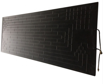
The panel functions as a large-surface-area, uninsulated solar water heater evaporator. Its design maximizes contact with the surrounding air to facilitate heat transfer. Unlike insulated hot water tanks, this component is designed to be completely exposed to the elements to maximize thermal conductivity.
The expansion valve dictates the state of the refrigerant entering the panel. Uniform heat distribution across the panel surface is critical for efficiency. If the heat is not distributed evenly, the refrigerant may not vaporize completely. This results in a mixture of liquid and gas returning down the line set.
Improper positioning causes uneven boiling of the refrigerant. This leads to wet vapor entering the compressor, which lowers overall system COP and can potentially damage the equipment over time. Compressors are designed to compress gas, not liquid. Liquid slugging can destroy the internal valves and scroll mechanisms of the compressor unit.
Evaluating the three most common installation locations based on property constraints and architectural limitations is essential. Each option presents unique advantages and challenges. Installers must weigh the physical realities of the building against the aerodynamic needs of the panel.
Side walls are the most common domestic and commercial installation choice. They offer a practical balance of accessibility and performance. Mounting on a gable end or a large unobstructed exterior wall provides a massive surface area that is generally easy to reach with standard scaffolding or ladders.
The benefits include ease of access for maintenance, minimal structural reinforcement required, and protection from extreme weather conditions. Wall mounting often simplifies the routing of refrigerant lines. You can usually punch straight through the brickwork or siding directly into the utility room where the compressor block sits, keeping line sets incredibly short.
Drawbacks involve potential aesthetic concerns and localized wind-blocking from adjacent structures. Careful consideration of the building's surroundings is necessary to ensure adequate airflow. If the wall faces a narrow alleyway or is heavily shielded by a neighboring building, the air can become stagnant, reducing the panel's ability to extract heat efficiently.
Roof mounting provides maximum exposure to both ambient air currents and direct sunlight. This location often yields the highest potential efficiency. Roofs are generally free from the shading caused by trees, fences, and other ground-level obstructions.
Structural implications of wind loading on roof-mounted panels must be addressed. The roof must be capable of supporting the additional weight and wind resistance. Thermodynamic panels act like sails; when the wind hits them, it transfers significant force to the mounting brackets and the roof trusses below.
Flush-mounting on a pitched roof differs significantly from A-frame mounting on a flat roof. Pitched roofs naturally provide a tilt, while flat roofs require specialized brackets to achieve the necessary angle. On a flat roof, you must ensure the ballast or mechanical fixings do not compromise the waterproof membrane.
Conduct a structural survey of the roof trusses to verify load-bearing capacity.
Identify the prevailing wind direction to optimize panel orientation.
Select appropriate mounting hardware (flush mounts for pitched, A-frames for flat).
Calculate the required ballast or mechanical anchor depth for flat roof installations.
Plan the routing of the line set to minimize penetrations through the roofing membrane.
Ground and balcony options are viable for properties with restricted roof or wall space. They offer alternative solutions when traditional mounting is not feasible. These locations are often chosen for apartments or buildings with strict planning permissions regarding roof alterations.
Ground-level installations carry risks such as shading from vegetation, reduced airflow, and vulnerability to physical damage or debris accumulation. Regular maintenance is required to keep the area clear. Leaves, snow drifts, and even garden furniture can block airflow, creating a microclimate of cold, stagnant air around the panel.
Structural bracket requirements are critical to maintain strict horizontal alignment when mounting to balcony railings. The brackets must be robust enough to withstand wind and weather. Balcony mounts must also account for vibration; the slight hum of the refrigerant boiling and moving through the panel can sometimes transfer through the metal railings into the building structure.
Translating physical panel features into operational outcomes and compliance with manufacturer warranties requires strict adherence to technical guidelines. Ignoring these rules can lead to system failure. The internal geometry of the panel dictates how it must sit in the physical world.
The internal capillary structure of the panels is designed for a specific orientation. This design ensures optimal flow of the refrigerant during the phase change process. The channels are stamped into the aluminum in a specific pattern to manage the expansion of the gas.
Installing panels in a landscape (horizontal) position is strictly required by most manufacturers. This orientation ensures gravity assists, rather than hinders, the return of refrigerant gas to the compressor. The liquid enters at the bottom, boils, and the resulting gas rises naturally to the top header pipe.
Portrait installation leads to refrigerant pooling, compressor starvation, and voided manufacturer warranties. It is a critical error that must be avoided during installation. If mounted vertically, the compressor has to work against gravity to suck the heavy, cold gas down and out of the panel, which it is not designed to do.
A 15-degree minimum tilt rule is generally applied to thermodynamic panels. This angle is crucial for maintaining the panel's operational efficiency. Even if you are mounting the panel on a perfectly flat roof or a vertical wall, the bracket itself must introduce this angle.
This tilt is necessary for shedding rainwater, melting snow, and clearing condensation. It prevents ice build-up that acts as a thermal insulator and degrades performance. If a panel sits perfectly flat, water pools on the surface. When the panel drops below freezing, that water turns into a sheet of ice, blocking ambient heat from reaching the aluminum surface.
The material science of the outdoor roll bond heat absorber typically involves anodized aluminum. This material offers excellent thermal conductivity and corrosion resistance. The anodized coating protects the metal from salt spray in coastal areas and general atmospheric degradation.
The roll bond manufacturing process creates internal micro-channels. Positioning impacts the thermal conductivity of the panel surface when exposed to varying wind directions. The channels must be aligned so that the prevailing wind sweeps across them, maximizing the convective heat transfer coefficient.
The ideal angle maximizes both wind-driven convection and rain-shedding self-cleaning properties. Finding this balance is key to long-term performance. A panel that cleans itself during a rainstorm maintains a higher efficiency than one that accumulates dust and bird droppings over time.
Local microclimates dictate positioning strategy and mitigate the risk of system underperformance. Understanding the specific environmental conditions of the installation site is vital. A system installed in a coastal region will behave differently than one installed in a dense urban center.
Installing in cold climates presents challenges. While the system works below freezing, the COP drops as the ambient temperature decreases. The compressor has to work harder and run longer to extract the same amount of heat from -10°C air as it would from 15°C air.
Though thermodynamic panels can run in complete shade, doing so in extremely cold climates removes the solar radiation buffer. This can significantly impact the system's efficiency during winter months. In these environments, relying solely on ambient air without any direct solar gain pushes the system to its lower operational limits.
Strategies for positioning panels in cold climates include capturing any available winter sun. South- or West-facing orientations can offset the lower ambient air temperatures and boost COP. By catching the low winter sun, the panel surface temperature rises slightly above the ambient air temperature, providing a much-needed efficiency boost during the coldest months.
A steady breeze is highly beneficial for thermodynamic panels. It replaces the pocket of cooled air around the panel with fresh ambient air, maintaining a high rate of heat transfer. Without wind, the panel cools the air immediately touching it, creating an insulating layer of cold air that reduces further heat extraction.
There is a trade-off between seeking high wind exposure for efficiency and the need for heavy-duty mounting hardware. The hardware must prevent structural failure under high wind loads. You want the panel exposed to the breeze, but not positioned in a wind tunnel effect between two buildings where gale-force gusts could rip the fixings out of the masonry.
Wind Speed (m/s) | Heat Transfer Impact | Structural Risk Level |
|---|---|---|
0 - 1 (Calm) | Poor (Cold air pooling) | Low |
2 - 5 (Light Breeze) | Optimal (Steady air replacement) | Low |
6 - 10 (Moderate Wind) | Excellent (High convection) | Medium (Requires standard secure fixings) |
11+ (Strong Gale) | Marginal gain over moderate | High (Requires reinforced brackets/anchors) |
Balancing the ideal physical location with the realities of installation costs and mechanical limitations is a necessary step in the planning process. A holistic approach ensures the best overall value. You cannot look at the panel in isolation; it is one half of a split system.
The relationship between panel distance from the indoor heat pump/compressor and system efficiency is direct. Shorter distances generally result in better performance. The copper pipes carrying the refrigerant act as a source of thermal loss and friction.
Excessive pipe runs increase installation costs due to the need for more copper and refrigerant. They also cause pressure drops that force the compressor to work harder, lowering overall COP. If the panel is on the roof and the compressor is in the basement, the compressor must push the fluid up three stories, fighting gravity and pipe friction the entire way. Keep the line set under 15 meters whenever possible.
Assessing the structural integrity of the chosen mounting surface is a fundamental requirement. The surface must be able to support the system safely. A single panel might only weigh 8 to 12 kilograms, but when wind gets behind it, the pull-out force on the bolts can exceed several hundred kilograms.
Hidden costs of reinforcing roofs or walls to handle the specific weight and wind-shear profile of thermodynamic panels should be factored into the initial budget. Proper planning prevents unexpected expenses. Using chemical anchors in old brickwork or adding sister joists to a roof structure adds labor and material costs that must be accounted for during the initial site survey.
Select a mounting location that prioritizes unobstructed ambient airflow over direct sunlight, keeping the panel away from narrow alleys or dense vegetation.
Verify that the chosen wall or roof structure can handle the wind-shear loads associated with the panel's surface area.
Ensure the installation strictly adheres to a landscape orientation and a minimum 15-degree tilt to guarantee proper refrigerant flow and water drainage.
Measure the proposed line set route to keep the distance between the outdoor panel and the indoor compressor as short as physically possible.
A: No. They extract heat from ambient air, wind, and rain. They function 24/7 even in complete shade. Direct sunlight improves efficiency by accelerating the refrigerant phase change, but it is not required for baseline operation.
A: Yes. Wall mounting is a common choice for domestic installations due to ease of access and minimal structural reinforcement. The panel must be mounted in a landscape orientation, and the bracket must provide a slight tilt.
A: Landscape orientation ensures gravity assists the return of refrigerant gas to the compressor. The internal capillary channels are designed for this flow path. Portrait installation causes refrigerant pooling and compressor starvation.
A: A minimum tilt of 15 degrees is required. This angle facilitates the runoff of rainwater, condensation, and melting snow. It prevents ice build-up that can insulate the panel and reduce thermal performance.
A: Longer line sets between the panel and the compressor increase pressure drops and thermal losses. This forces the compressor to work harder, reducing the overall Coefficient of Performance (COP) and increasing installation costs.
A: Yes, but it is generally discouraged unless airflow is completely unobstructed. Ground installations are vulnerable to shading from vegetation, debris accumulation, and physical damage, all of which reduce system efficiency.


