 English
Views: 7 Author: Site Editor Publish Time: 2026-08-08 Origin: Site


Stricter global energy consumption regulations require appliance manufacturers to maximize the thermodynamic efficiency of every refrigeration cycle component. Agencies like the DOE and ENERGY STAR continually lower permissible power limits, forcing engineering teams to rethink standard designs. The heat rejection phase remains a primary bottleneck in system efficiency. Suboptimal geometry in a Refrigerator Condenser forces the compressor to run longer, increasing power draw and accelerating component wear over time.
Achieving an energy efficient fridge condenser requires moving beyond basic material upgrades to rigorously evaluating tube layout, pitch optimization, and airflow dynamics. This guide breaks down how specific structural configurations impact thermal performance, manufacturing scalability, and lifecycle energy use. You will learn how to balance spatial constraints with maximum heat transfer to meet modern regulatory standards.
Tube Pitch Dictates Performance: Optimizing the distance between condenser tubes (tube pitch) minimizes thermal resistance and maximizes natural convection, directly reducing compressor workload regardless of the overarching geometry.
Geometry vs. Spatial Constraints: Transitioning from traditional wire-on-tube to hot-wall or microchannel layouts involves strict trade-offs between available cabinet space, heat transfer coefficients, and manufacturing costs.
System Synergy is Essential: The most efficient tube layouts are designed to work in tandem with modern variable-speed compressors and smart control systems, allowing for precise thermal management.
Fouling Mitigation is Critical: Highly dense tube layouts may perform well in lab conditions but suffer rapid efficiency degradation in real-world environments due to dust accumulation, necessitating designs optimized for cleanability.
Surface Modifications Compound Layout Gains: Pairing an optimized layout with surface treatments enhances condensate drainage and thermal conductivity, sustaining baseline energy efficiency over the appliance's lifespan.
The primary function of any refrigeration heat exchanger is rejecting absorbed heat to the ambient environment. The refrigerant absorbs thermal energy from the interior cabinet and travels to the condenser as a high-pressure, high-temperature gas. The physical layout must facilitate a rapid phase change from gas to liquid. We measure success by how effectively the design lowers the condensation temperature. A lower condensation temperature directly reduces compressor power consumption. When the compressor works against a lower head pressure, it draws less electrical current.
The heat rejection process inside the tubes happens in three distinct phases:
Desuperheating: The layout must quickly strip sensible heat from the hot discharge gas exiting the compressor.
Condensing: The bulk of the heat exchanger surface area handles the latent heat of condensation, turning the saturated vapor into a liquid.
Subcooling: The final passes of the tube layout drop the liquid refrigerant temperature below its saturation point, ensuring a solid column of liquid reaches the expansion device.
Evaluating success requires looking at the heat rejection rate under varying ambient conditions. Engineers prioritize designs that maintain low condensation temperatures even during peak load periods, such as immediately after a defrost cycle or when the user loads warm groceries into the cabinet.
Tube arrangement dictates the airflow path across the heat exchanger surface. This path determines the convective heat transfer coefficient. An optimized layout channels ambient air smoothly over the heated tubes. Poorly arranged tubes create dead zones where air stagnates. Stagnant air insulates the tubes and traps heat. The layout must balance surface area exposure with airflow continuity.
Altering the distance between tubes changes how air behaves as it rises. Natural convection relies entirely on buoyancy forces generated by heat. If tubes block this upward draft, efficiency drops sharply. You cannot achieve top-tier energy ratings with a restrictive tube arrangement. The geometry must encourage a continuous updraft, pulling cool air from the floor and exhausting warm air out the back or top of the appliance housing.
The physical footprint and total tube length must perfectly match the compressor's volumetric capacity. Mismatched components lead to severe operational inefficiencies. An undersized layout cannot reject heat fast enough, forcing continuous, inefficient compressor operation. An oversized layout may cause short-cycling. Short-cycling wears out compressor relays and spikes startup power surges.
Engineers calculate the required heat rejection capacity based on cabinet volume, insulation thickness, and target internal temperatures. They translate this requirement into specific tube lengths, bend radii, and fin densities. The geometry must fit within the designated appliance housing while meeting these capacity demands. Proper capacity matching ensures the system reaches thermal equilibrium quickly after startup.
Evaluating performance requires establishing strict baseline metrics. Heat rejection capacity is the primary indicator of thermal performance. Pressure drop measures the resistance the refrigerant faces inside the tubes. High internal pressure drop forces the compressor to work harder, negating thermal gains. The footprint-to-capacity ratio evaluates how effectively space is utilized.
Standard Condenser Evaluation Metrics
Metric Category | Measurement Focus | Impact on Energy Use |
|---|---|---|
Heat Rejection Capacity | Watts of heat dissipated per hour | Higher capacity lowers compressor run time. |
Internal Pressure Drop | Refrigerant flow resistance (kPa) | Lower drop reduces compressor mechanical load. |
Airflow Resistance | Static pressure across the coil (Pa) | Lower resistance maximizes natural convection cooling. |
Footprint-to-Capacity | Heat rejection per square inch | Optimizes limited cabinet space for maximum efficiency. |
Engineering consensus places heavy emphasis on tube pitch optimization. Tube pitch is the center-to-center distance between adjacent tubes. Finding the exact pitch threshold prevents thermal boundary layer interference. As air heats up around a tube, a thermal boundary layer forms. If tubes are too close, these layers merge. Merged layers restrict airflow and trap heat.
Research indicates that identifying the universal optimal tube pitch minimizes energy consumption. This holds true despite variations in the broader condenser geometry. Widening the pitch improves airflow but reduces total surface area within a given footprint. Narrowing the pitch increases surface area but chokes natural convection. Engineers use computational fluid dynamics (CFD) models to pinpoint the exact spacing that balances these opposing forces. For standard natural convection designs, a pitch of 50mm often provides the best balance, though this varies based on tube diameter.
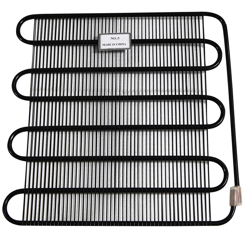
The traditional home refrigerator condenser coil often utilizes a wire-on-tube design. Steel wires are resistance-welded perpendicular to the refrigerant tubes. This increases the extended heat transfer surface. Wire-on-tube layouts are highly effective for natural convection because the thin wires offer minimal resistance to upward airflow.
Hot-wall designs take a different approach. Tubes are taped or glued directly to the inside of the outer cabinet walls before the polyurethane insulation is injected. Hot-wall designs rely entirely on the appliance's exterior steel skin to dissipate heat. They require specific spacing to avoid heat trapping within the insulation. Wire-on-tube layouts typically offer better raw heat transfer rates. Hot-wall designs offer aesthetic benefits and prevent exterior condensation in humid climates. Evaluating the energy consumption profiles of both reveals distinct trade-offs. Hot-wall units often require slightly longer compressor run times in warm climates because the heat transfer coefficient of the flat cabinet wall is lower than that of exposed wire-on-tube coils.
High-efficiency units are shifting toward microchannel tube layouts. Microchannel designs use flat, extruded aluminum tubes with multiple internal ports. They feature highly dense, louvered fins brazed between the tubes. This creates massive surface-area-to-volume ratios. Microchannel layouts reject heat exceptionally well in compact spaces.
However, they introduce the risk of higher internal refrigerant pressure drops. The tiny internal ports restrict fluid flow more than standard 1/4-inch or 5/16-inch round tubes. Engineers must size the compressor appropriately to handle this resistance. Microchannel layouts also require forced-air cooling via a condenser fan. This adds a small electrical load to the system. Despite the fan motor draw, the overall energy savings are often substantial. The compact nature allows manufacturers to increase cabinet insulation thickness, further reducing the overall heat load on the system.
Staggered versus aligned tube layouts drastically impact air velocity and turbulence. Aligned layouts place tubes directly behind one another in the direction of airflow. This creates low airflow resistance but poor heat mixing. Staggered layouts offset the tubes in each row. This forces air to weave through the bundle.
Staggering creates necessary turbulence for effective heat transfer. Turbulence disrupts the thermal boundary layer, exposing fresh, cool air to the hot tubes. However, there is a strict trade-off. Excessive turbulence causes severe airflow restriction. If resistance is too high, natural convection stalls entirely. Engineers calculate the Reynolds number for the specific layout to predict flow behavior. They aim for a flow regime that maximizes heat transfer without choking the draft. In forced-air systems, high resistance means the fan motor must work harder, drawing more watts and reducing the net efficiency gain.
An optimized tube layout enables modern refrigeration control systems to function at peak efficiency. Variable-speed (inverter) compressors adjust their RPM based on real-time cooling demand. A highly efficient layout allows these compressors to run at lower, more efficient speeds for longer durations. If the layout rejects heat poorly, the compressor must ramp up to high RPMs to force the heat out. High RPM operation consumes significantly more electricity and generates more mechanical noise.
Layout efficiency is maximized when paired with intelligent sensors. These sensors modulate cooling based on ambient temperature and internal load. The system dynamically adjusts to changes in the kitchen environment. The physical layout provides the thermal headroom for the software to optimize power draw. Hardware and software must work in perfect synergy. A highly advanced inverter compressor will still waste energy if paired with a restrictive, poorly pitched refrigerator condenser.
Altering the external surface of the tubes yields measurable efficiency gains. Techniques include dimpling, finning, or applying hydrophilic coatings. Dimpling creates internal turbulence in the refrigerant flow, improving heat transfer from the fluid to the tube wall. Finning vastly increases the external surface area available for air contact.
Hydrophilic coatings reduce fouling and improve condensate drainage during defrost cycles. These modifications enhance overall thermal conductivity. Engineers evaluate the return on investment for surface modifications during the prototyping phase. Sometimes, simply increasing the physical size of the layout is cheaper. However, when space is constrained by the appliance chassis, surface enhancements are mandatory. They sustain baseline energy efficiency over the appliance's lifespan by preventing performance degradation.
Material selection directly dictates which tube layouts are physically manufacturable. Copper offers exceptional thermal conductivity. It transfers heat rapidly but is expensive and heavy. Aluminum is lighter and cheaper, with very good thermal properties. Steel is the most rigid and cost-effective but has lower thermal conductivity.
Material Thermal Properties for Condenser Manufacturing
Material | Thermal Conductivity (W/m·K) | Manufacturing Characteristics | Common Application |
|---|---|---|---|
Copper | ~400 | Highly malleable, easy to braze, expensive. | Premium commercial units, tight bends. |
Aluminum | ~235 | Lightweight, prone to galvanic corrosion if mixed. | Microchannel layouts, modern domestic units. |
Low-Carbon Steel | ~45 | Rigid, requires wider bend radii, cheap. | Traditional wire-on-tube, hot-wall designs. |
Material rigidity determines the minimum bend radius for the tubes. Tight layouts require highly malleable materials like aluminum or copper. Steel requires wider sweeping bends, which increases the footprint. Engineers balance thermal conductivity with structural integrity. The chosen material must withstand internal operating pressures up to 300 PSI and external impacts during shipping. The layout design is fundamentally constrained by the physical properties of the selected metal.
Implementing tighter tube pitches or microchannel designs introduces significant manufacturing complexities. Precision CNC bending equipment is required to prevent tube kinking when forming tight radii. Welding dense fin arrays demands advanced controlled-atmosphere brazing techniques. These requirements elevate tooling costs and increase production time on the assembly line.
Material waste can also rise during the transition to a new layout. Engineers quantify these upfront costs against long-term energy savings. Regulatory compliance often forces manufacturers to absorb these costs to keep products on the market. A highly efficient layout commands a premium retail price, but the production line must be retooled to handle tighter tolerances. Quality control becomes more stringent to ensure no internal blockages occur from excess brazing flux during manufacturing.
Integrating optimal tube layouts into modern appliance footprints is a major engineering challenge. Consumer demand favors counter-depth refrigerators with maximum internal volume. This leaves very little space for the mechanical compartment at the bottom rear of the chassis. The heat exchanger must be compacted without losing capacity.
Engineers often utilize the vertical space along the back wall for static coils. For forced-air systems, they fold the layout into a compact block underneath the cabinet. Form-factor constraints limit the use of ideal, wide-pitch natural convection designs. Forced-air compact layouts become necessary. The design must accommodate the compressor, drain pan, defrost timer, and wiring harnesses. Spatial limitations dictate the final geometry more than any other single factor.
A newly optimized layout must be scalable across different refrigerator models. Manufacturers cannot design a unique heat exchanger for every single unit in their catalog. They develop modular layouts that can be lengthened or shortened by adding or removing tube passes. Scalability reduces inventory complexity and standardizes production.
However, scaling must maintain regulatory compliance across all sizes. A layout that achieves an ENERGY STAR rating on a 15-cubic-foot unit might fail on a 25-cubic-foot model due to the non-linear increase in heat load. Engineers conduct extensive scaling tests in psychrometric chambers. They verify that the footprint-to-capacity ratio holds true as the physical size increases. Consistent compliance requires a robust, adaptable base design.
Highly dense tube layouts trap dust, dirt, and pet hair rapidly. This debris acts as a thermal insulator. It blocks airflow and spikes energy consumption. Day-one laboratory efficiency ratings often ignore this reality. In a controlled lab, a dense layout performs flawlessly. In a real-world kitchen, performance degrades within months.
The compressor runs longer to compensate for the insulated tubes. Long-term degradation can increase power draw by up to 30%. Engineers analyze the fouling rates of proposed designs using standardized dust testing. They ensure the spacing allows dust to pass through or be easily removed. Sustained real-world performance is the true measure of layout success. A coil that clogs in three months is a failed design, regardless of its initial lab rating.
User habits drastically alter the heat rejection load. Setting the refrigerator 10 degrees colder than recommended can spike energy use by up to 25%. Loading the cabinet with warm groceries creates a massive thermal spike. The layout must handle these elevated internal heat loads without bottlenecking.
If the heat exchanger cannot dissipate the sudden influx of heat, internal temperatures rise. The compressor runs continuously, risking thermal overload. An optimized layout provides a thermal buffer. It possesses the capacity to reject heat rapidly during peak demand. Designing only for steady-state operation leads to field failures. The geometry must accommodate worst-case user scenarios and extreme ambient summer temperatures.
Engineers balance optimal thermodynamic spacing with physical cleanability. Users must be able to vacuum or brush the coils easily. If the layout is too dense, cleaning becomes impossible without specialized compressed air tools. Uncleanable designs guarantee long-term efficiency loss.
Layout choices directly impact the recommended maintenance frequency. A wide-pitch layout might require cleaning every 12 months. A dense microchannel layout might need attention every 3 to 6 months. Manufacturers provide clear access panels to facilitate this. The physical orientation of the tubes should allow debris to fall away rather than wedging deeper into the fin pack. Designing for maintenance ensures the appliance retains its energy rating throughout its lifespan.
Initiate computational fluid dynamics (CFD) modeling to pinpoint the exact optimal tube pitch for your specific cabinet dimensions and airflow constraints.
Prototype high-potential staggered and aligned layouts to measure real-world pressure drops against theoretical calculations in a psychrometric chamber.
Conduct long-term fouling tests using standardized dust mixtures to evaluate maintenance frequency and efficiency degradation over a simulated 10-year lifespan.
Integrate layout designs with variable-speed compressor control algorithms to maximize low-RPM operational time and reduce acoustic noise.
A: Optimal tube pitch prevents thermal boundary layer interference between adjacent tubes. When spaced correctly, natural convection is maximized, allowing heat to dissipate rapidly. This reduces the compressor's workload and lowers overall energy consumption, regardless of the broader condenser geometry.
A: The most efficient layout depends on specific appliance constraints. Microchannel designs offer massive surface area for compact spaces but require fans. Optimized wire-on-tube designs excel in natural convection setups. The best layout balances airflow availability, cabinet space, and integration with smart control systems.
A: Dense geometries rapidly accumulate dust, dirt, and pet hair. This debris acts as a powerful insulator, trapping heat and severely restricting airflow. As heat rejection drops, the compressor runs longer, spiking energy use. These tight layouts necessitate thorough cleaning every 3 to 6 months.
A: Hot-wall condensers integrate tubes into the appliance exterior, relying entirely on natural convection. They require specific tube spacing to prevent heat from trapping against the insulation. While they prevent exterior condensation, they often require slightly longer compressor run times compared to optimized exposed coils.
A: Yes. Surface treatments like dimpling, finning, or hydrophilic coatings improve thermal conductivity and aid in condensate drainage. These modifications also reduce fouling rates, which helps sustain the appliance's long-term baseline energy efficiency without increasing the physical footprint.
A: High airflow resistance chokes natural convection, drastically lowering heat rejection rates. This forces the compressor to operate against higher head pressures and run for longer cycles. The impact is especially severe when users set internal temperatures excessively low, causing significant energy spikes.


