 English
Views: 6 Author: Site Editor Publish Time: 2026-08-09 Origin: Site


High compressor discharge pressure acts as a primary driver of catastrophic compressor failure. It causes excessive energy consumption and leads to the thermal degradation of oil in low-temperature refrigeration systems. Facility managers and industrial operators frequently misdiagnose this high head pressure as a direct compressor fault. This misdiagnosis leads to expensive and unnecessary equipment replacements. In reality, the actual bottleneck usually stems from inadequate or compromised heat rejection at the condenser level.
Addressing high discharge pressure requires a systemic evaluation of the entire heat rejection cycle. Upgrading, resizing, or optimizing the deep freezer condenser provides a verifiable, long-term solution. It stabilizes system pressures, reduces mechanical wear, and lowers operational demands.
Direct Correlation: A deep freezer condenser dictates the condensing temperature; improving its heat transfer efficiency directly lowers the pressure the compressor must pump against.
Maintenance vs. Replacement: Before capital expenditure, operators must rule out airflow restrictions (fouling), system overcharging, and non-condensables, which artificially inflate discharge pressure.
Design Matters: Upgrading to a specialized low temperature freezer coil with optimized fin spacing or microchannel technology significantly enhances commercial freezer heat rejection.
System Balance: Lowering discharge pressure saves energy, but systems require precise head pressure controls (like operator-selected fan cycling setpoints) to prevent thermal expansion valve (TXV) starvation during low ambient conditions.
Defining normal versus high discharge pressure depends entirely on the specific refrigerant properties and the ambient air temperature entering the condenser coil. Refrigeration engineers look at the temperature difference between the ambient air and the condensing temperature of the refrigerant. A standard air-cooled system typically operates with a condensing temperature 10°F to 30°F above the ambient air. When the discharge pressure exceeds the manufacturer's design envelope, the compression ratio spikes. The primary goal of system optimization is achieving a compression ratio that maximizes volumetric efficiency without exceeding the compressor's thermal limits. Operating outside this envelope drastically reduces the mass flow rate of the refrigerant, meaning the system works harder to move less heat.
Field technicians determine the target head pressure using a specific sequence of measurements:
Measure the ambient air temperature entering the condenser coil using a calibrated digital thermometer.
Add the manufacturer-specified condenser split to the ambient temperature reading.
Convert this target condensing temperature to pressure using a Pressure-Temperature (PT) chart for the specific refrigerant in the system.
Compare the calculated target pressure against the actual gauge reading on the high side of the compressor.
Understanding discharge pressure requires mapping the relationship between the evaporator, compressor, and condenser. The evaporator absorbs heat from the freezer space, boiling the liquid refrigerant into a low-pressure gas. The compressor acts as a vapor pump. It draws in this low-pressure gas and compresses it into a high-pressure, high-temperature superheated vapor. The compressor must overcome the pressure established by the condenser to push the refrigerant forward. If the condenser fails to reject heat efficiently, the pressure in the high side of the system backs up. The compressor must then generate even more force to move the refrigerant, creating a compounding cycle of mechanical stress and heat generation.
High discharge pressure uniquely impacts different compressor architectures. Reciprocating compressors rely on internal pistons and valve plates. When forced to pump against abnormally high head pressure, the discharge valves flex beyond their design limits, eventually fracturing. The extreme heat of compression also breaks down the internal lubricating oil, causing it to lose viscosity. Polyolester (POE) oils begin to carbonize when discharge temperatures exceed 225°F. This leads to rapid bearing wear and catastrophic mechanical seizure. Scroll compressors face different vulnerabilities. The continuous orbital motion relies on tight tolerances between the scroll flanks. Excessive discharge pressure causes the scroll tips to overheat and wear down, destroying the compressor's ability to create a seal and pump refrigerant effectively.
Mechanical failures often stem from external system faults rather than internal defects. A system overcharge occurs when technicians add too much refrigerant. This excess liquid backs up into the bottom passes of the condenser coil. By filling the tubes with liquid, the overcharge reduces the internal volume available for the hot discharge gas to condense. This loss of surface area forces the remaining gas to condense at a much higher pressure. Fouling presents a similar physical barrier. Dirt, dust, and debris clog the external fins of the condenser. This debris acts as a thermal insulator and blocks airflow. The clogged condenser prevents ambient air from absorbing heat, forcing the refrigerant to retain its thermal load and artificially inflating the discharge pressure.
Operators must recognize the operational red flags before mechanical failure occurs. The most obvious symptom is frequent tripping of the high-pressure safety switch. This switch shuts down the compressor to prevent a localized rupture. Technicians will also observe a significant increase in electrical amperage draw, as the compressor motor requires more current to overcome the high head pressure. Elevated discharge line temperatures provide another clear warning sign. If the discharge line temperature exceeds 225°F, the system is actively destroying its lubricating oil. Inside the freezer space, users will notice reduced cooling capacity and longer run times, as the inefficient system struggles to maintain the setpoint temperature.
The condenser serves as the primary mechanism for heat rejection in any refrigeration circuit. Increasing the physical footprint or optimizing the internal geometry allows for more efficient thermodynamic phase changes. The coil must perform three distinct functions: desuperheating the hot discharge gas, condensing the vapor into a liquid, and subcooling that liquid below its saturation temperature. A larger surface area provides the necessary space for the refrigerant to shed its thermal load into the ambient air. When a system utilizes a properly sized low temperature freezer coil, the refrigerant condenses at a lower temperature. This directly dictates a lower saturation pressure, immediately relieving the mechanical burden on the compressor.
Physical surface area means nothing without adequate airflow. Condenser fans pull or push ambient air across the coil fins, carrying away the rejected heat. Upgrading fan blade design improves the volumetric flow rate of air moving through the system. Utilizing Electronically Commutated (EC) motors offers precise control over fan speed. These motors adjust their RPM based on real-time pressure readings, maintaining an optimal temperature difference (Delta-T) between the air and the refrigerant. By moving more air with less electrical input, advanced fan configurations drive down the condensing pressure while simultaneously reducing the parasitic energy load of the condenser unit itself.
A properly functioning condenser does more than just lower head pressure; it ensures system stability through subcooling. Subcooling refers to cooling the liquid refrigerant below its condensing temperature. This process occurs in the final passes of the condenser coil. Adequate subcooling guarantees that a solid, bubble-free column of liquid refrigerant reaches the thermal expansion valve. If the condenser is undersized or fouled, the liquid leaves the coil at a higher temperature, causing it to flash into gas before reaching the metering device. Flash gas starves the evaporator of liquid, drastically reducing cooling capacity and forcing the compressor to run continuously to meet the load.
Technicians verify proper condenser function by measuring subcooling directly at the unit:
Attach a calibrated high-pressure gauge to the liquid line service port.
Read the saturation temperature from the gauge for the specific refrigerant.
Clamp a calibrated thermocouple to the liquid line near the condenser outlet.
Subtract the measured line temperature from the saturation temperature to find the subcooling value.
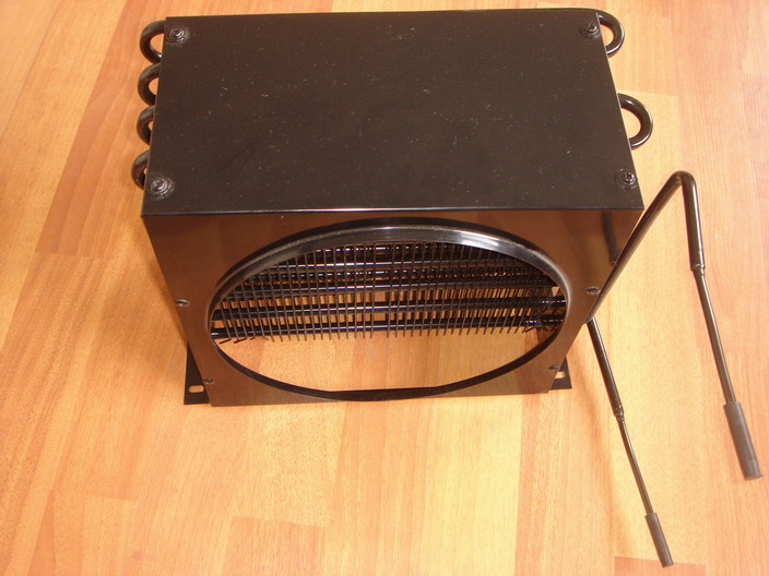
Facility operators must choose the right heat rejection method based on their specific environmental and operational constraints. Standard air-cooled condensers dominate the commercial refrigeration sector due to their simplicity and lack of water requirements. They rely entirely on ambient air, making them highly sensitive to summer heatwaves. Evaporative condensers utilize a water spray system over the coil, leveraging the latent heat of vaporization to reject massive amounts of heat. These units are frequently utilized in large-scale industrial applications or indirect ammonia chillers. While evaporative models offer superior peak heat rejection efficiency and lower discharge pressures during hot weather, they require strict water treatment protocols to prevent scale buildup and biological growth.
Engineering a reliable refrigeration system requires sizing the condenser for the highest historical ambient temperatures, known as design conditions. Sizing a unit based on average yearly temperatures guarantees system failure during peak summer months. When the ambient temperature spikes, the condenser loses its ability to reject heat efficiently. The condensing pressure rises rapidly to compensate for the reduced temperature difference between the air and the refrigerant. By intentionally oversizing the condenser for peak conditions, engineers ensure the compressor remains within its safe operating envelope even during extreme heatwaves, preventing nuisance trips and product loss.
The internal construction of the condenser coil dictates its overall heat transfer coefficient. Traditional coils utilize copper tubes mechanically expanded into aluminum fins. This proven technology offers robust durability and straightforward repair procedures. However, the industry is rapidly adopting aluminum microchannel coils for enhanced commercial freezer heat rejection. Microchannel coils feature flat, multi-port aluminum tubes brazed to louvered aluminum fins. This design significantly increases the heat transfer surface area while reducing the internal volume. Microchannel coils require up to 30% less refrigerant charge than traditional fin-and-tube designs. Furthermore, the all-aluminum construction eliminates the risk of galvanic corrosion that occurs when dissimilar metals, like copper and aluminum, are exposed to moisture and salt.
Condenser Coil Architecture Comparison
Design Style | Heat Transfer Efficiency | Refrigerant Charge Requirement | Corrosion Resistance | Field Serviceability |
|---|---|---|---|---|
Traditional Fin-and-Tube (Copper/Aluminum) | Standard baseline performance | High internal volume requires larger charge | Susceptible to galvanic corrosion in coastal areas | Easier to clean, field repairable with standard brazing |
Microchannel (All-Aluminum) | High efficiency due to increased surface contact | Up to 30% reduction in required system charge | Excellent resistance to galvanic corrosion | Requires careful cleaning to avoid bending delicate fins; difficult to field repair |
Evaporative Condenser | Maximum efficiency via latent heat of vaporization | Varies based on specific system architecture | Requires heavy protective coatings against water scale | High maintenance; demands strict water treatment and chemical balancing |
Environmental regulations are forcing the transition to low-GWP (Global Warming Potential) refrigerants and natural alternatives like CO2 and Ammonia. Condenser design must adapt to the unique thermodynamic properties of these modern fluids. CO2 systems, for example, operate at significantly higher pressures than legacy HFC refrigerants. A condenser built for R-404A cannot withstand the bursting pressure requirements of a transcritical CO2 cycle. When evaluating a condenser upgrade, operators must ensure the new unit is rated for the specific operating pressures and mass flow characteristics of the intended refrigerant. Upgrading the heat rejection hardware provides an opportunity to future-proof the facility against upcoming regulatory phase-downs.
While lowering discharge pressure saves energy and reduces compressor wear, dropping the pressure too far introduces severe operational risks. During winter months, cold ambient air strips heat away from the condenser too rapidly. This causes the head pressure to float downward. If the condensing pressure falls below a critical threshold, the system loses the pressure drop required to push liquid refrigerant through the thermal expansion valve. This starves the evaporator, causing the suction pressure to plummet and potentially freezing the coil. To mitigate this risk, systems require head pressure control valves or operator-selected setpoints for fan cycling. These controls actively reduce condenser capacity during cold weather, artificially holding the discharge pressure high enough to keep the metering device functioning properly.
Replacing or modifying a condenser requires strict adherence to safe refrigerant handling procedures. Technicians must perform a proper pump-down procedure to isolate the refrigerant in the receiver tank. This process involves closing the liquid line valve and allowing the compressor to pull the remaining refrigerant out of the evaporator and suction line. Pumping down the system minimizes refrigerant loss and prevents environmental venting during component replacement. Once the new condenser is installed, the total system charge must be recalculated. A larger, high-efficiency coil possesses a different internal volume than the original unit. Failing to adjust the refrigerant charge accordingly will result in either an immediate overcharge condition or a starved system.
A standard pump-down sequence includes:
Front-seat the king valve on the receiver to stop liquid flow to the evaporator.
Run the compressor to pull the low-side pressure down.
Shut off the compressor manually when the suction pressure reaches 2 psig.
Close the discharge service valve to completely isolate the compressor and condenser.
Poor installation practices directly negate the benefits of a new condenser. If technicians fail to pull a deep vacuum on the system before introducing refrigerant, air and moisture remain trapped inside the piping. These non-condensable gases do not phase-change into liquid under normal refrigeration pressures. Instead, they migrate to the top of the condenser coil and occupy valuable internal space. By displacing the refrigerant, non-condensables drastically reduce the available surface area for heat transfer. This forces the discharge pressure to spike artificially, regardless of how large or efficient the new condenser coil might be. Utilizing a micron gauge and performing a triple evacuation process guarantees the system remains free of non-condensables.
Hook up a calibrated manifold gauge set to verify actual discharge pressure against ambient temperature baselines.
Recover excess refrigerant if the system exhibits high head pressure alongside high subcooling, indicating an overcharge.
Clean the condenser coil fins using a non-acidic foaming cleaner and a low-pressure water spray to restore airflow.
Measure the voltage and amperage of all condenser fan motors to identify failing bearings or weak capacitors.
Consult a licensed commercial refrigeration engineer to recalculate the required condenser surface area based on historical peak summer temperatures.
A: The primary causes include dirty condenser coils that block airflow, failed condenser fan motors, system overcharging that reduces internal coil volume, and the presence of non-condensable gases like air or moisture trapped inside the refrigeration circuit.
A: Dirt and debris act as a thermal insulator on the coil fins. This blockage prevents ambient air from flowing through the condenser to absorb heat. Consequently, the refrigerant retains its thermal load, forcing the saturation temperature and discharge pressure to rise rapidly.
A: Yes. A larger or more efficient coil lowers the condensing temperature. This reduces the compression ratio, meaning the compressor requires less electrical current to push the refrigerant through the system, directly lowering overall kilowatt consumption.
A: Floating head pressure is an energy-saving strategy that allows the condensing pressure to drop naturally as ambient outdoor temperatures decrease. Instead of maintaining a fixed, artificially high pressure year-round, the system reduces compressor workload during cooler weather.
A: Fans cycle off to maintain a minimum condensing pressure. If the pressure drops too low during winter, the thermal expansion valve loses the driving force needed to feed liquid refrigerant into the evaporator, which causes the system to stop cooling.
A: Cleaning frequency depends entirely on the operating environment. Standard commercial and industrial settings typically require quarterly cleanings. Units located near dusty agricultural areas, heavy traffic, or grease-laden restaurant exhausts require monthly maintenance.
A: A pump down is the process of using the compressor to move all the system's refrigerant into the condenser and receiver tank, where it is isolated by closing valves. This is necessary to perform safe maintenance or replace components without venting refrigerant.


